
 عربي
عربي عربي
عربي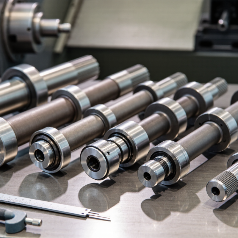
An armature shaft is the rotating steel core that carries an armature, commutator, fan, or drive gear. In brushed motors, it transfers electromagnetic torque to the mechanical load. Its centerline must remain stable under speed, heat, and repeated starting cycles.
The International Energy Agency reports that electric motor systems use roughly half of global electricity. This figure explains why shaft design affects more than mechanical reliability. A small imbalance can increase vibration, bearing wear, noise, and energy loss.
Core features include a precision-ground journal, controlled runout, suitable steel hardness, and a keyed or splined drive section. A shoulder may locate the armature accurately. A threaded end can secure a fan or coupling.
Material choice depends on torque, speed, and operating temperature. Low-carbon steel supports machining and case hardening, while alloy steel may improve fatigue resistance.
The U.S. Department of Energy identifies motor-system efficiency as a major industrial energy opportunity, making accurate shaft geometry commercially important. ISO 21940 balancing practices also provide a useful reference for rotor quality, though shaft requirements still depend on the complete assembly.
Tolerance alone is not enough. Surface finish, press-fit stress, and heat-treatment distortion can interact in unexpected ways. That is where many specifications become too optimistic.
Engineers should verify dynamic balance after assembly, not only inspect the shaft separately. Supplier records should include material certificates, hardness readings, dimensional reports, and traceable balancing results.